Minolta-35 … I’ll have seconds

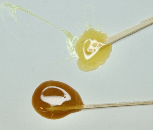
OK, so after the last restoration I will continue on with the next ones … which also needs the expected shutter curtain replacement.

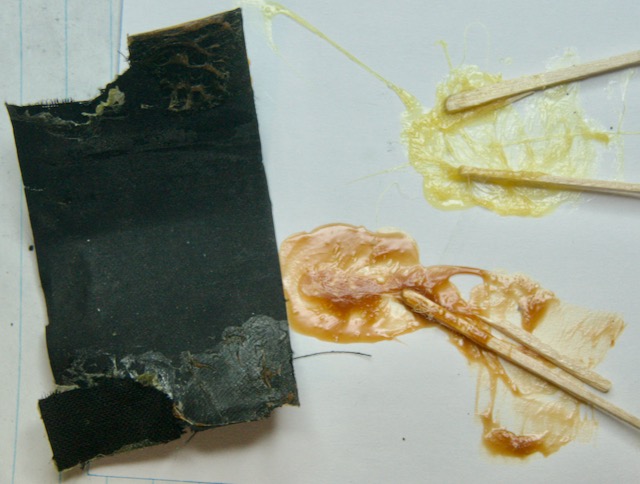
This time I will not take apart the gearing section to remove/free the rollers to avoid having to reposition all the gears … also I looked at the the possibility of replacing the curtains with just taking the film plane cover off only … not. Might as well take the innards out to do an clean … especially all those tiny black bits of the shutter curtain that have flaked off all those years.

Roll the film!!!

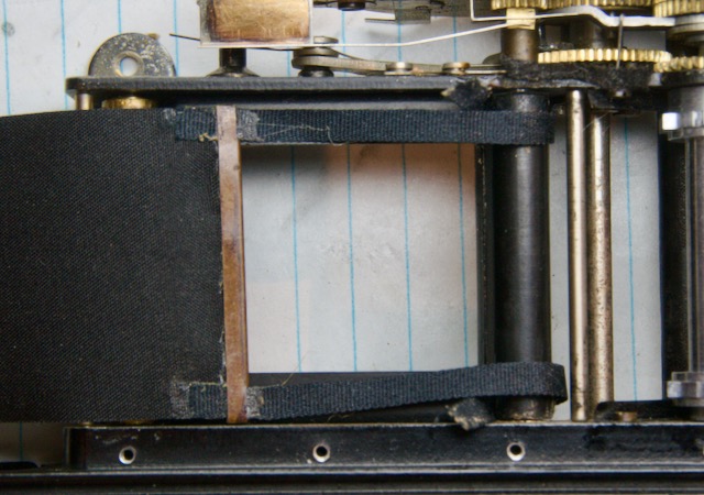
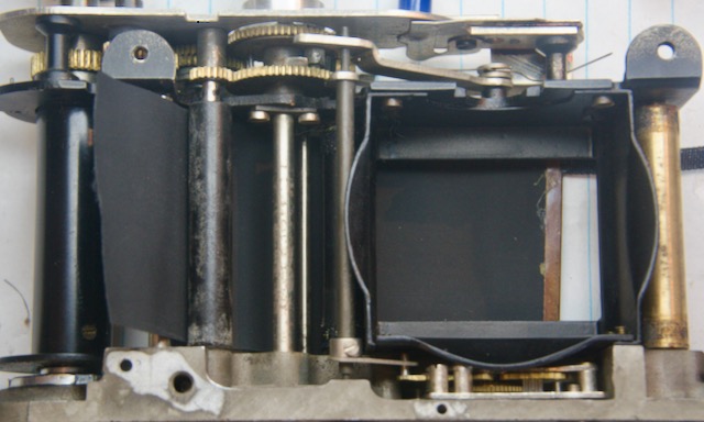
I examined one of the camera’s that I have with the old curtains still attached to see where they sit. The first curtain lath was taken up on the spring roller, and the second curtain lath sat just before the thin roller.

OK, so lets play around with positioning.

Set the shutter mechanism in its released position … move the gears it necessary.

I placed the first curtain on top of the left roller to see how much material I had. This time I place the lath left screw hole so it is sitting on top of its spring roller and 0.4mm before the thin roller … then I fed the tape over and around the black roller. Glued both tapes on the roller and checked the lath so that it is parallel with the thin roller.

Glue the curtain to the spring roller on the left. From the bottom turn the spring wind up screw until it starts winding up the curtain … do not over do it.

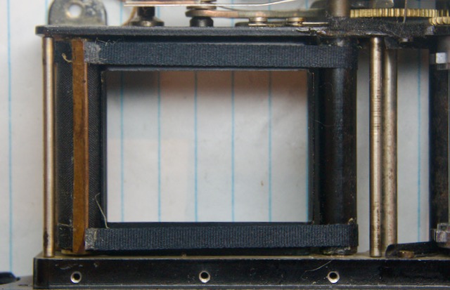
Wind up the shutter and release … watch that the first curtain moves freely. Next up is the second curtain. I positioned the lath to sit on top of the thin roller … and let that set.

OK, so now to check the shutter … looks good. The timing of the higher speeds was pretty good, but I ran into a problem with the low speeds.

The speeds 1/25s and lower are controlled by the slow speed escapement gears. When the 25-1 speed is set … when the shutter is triggered the first curtain is released. A spring on the bottom of the camera is pressed which pushes the slow speed post upwards. When the second curtain is released the pin under one of the gears contacts the arm at the top of the slow speed post. This forces the arm to revolve. At the bottom of this arm it engages the gears of the escapement, thus slowing the release at the post turns.

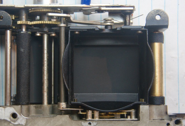
What I found out is that if the second curtain lathe is positioned to the far left it will be seen slowly move across the film gate opening. So as the slow speed arm is rotating, the second curtain roller is slowly unfurling the curtain, before it is finally released. So this means the film is not exposed equally (underexposed on one side).

I have to remove the curtains and move the lath position further away from the spring rollers … I did figure out that the lath positioning from the previous post was correct, let it sit on the last bottom screw hole.

Back to square one.

First curtain tape gets attached to black roller. Reposition the length so that the lath is sitting on last screw hole and tension on tape is equal. Then attach the curtain to the spring roller.

Next up is the second curtain.

I attached the curtain first. Pass it through the guides then through to the roller. I sat the lath past the first one by about 1mm … then I attched the tape, making sure they both have equal tension.

Speed check. First release the spring tension on both rollers. Then put two rotations on the first curtain and three on the second … check shutter speeds between 1/35-1/500s. I like to increment 1/2 rotations after this to speed up the timing.

SONY DSC

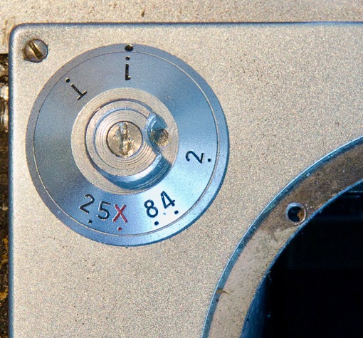
Once you are satisfied with the tension you can tackle the slow speeds. If the slow speeds are off, take of the slow speed dial cap (should be a single grub screw). In the middle there is a screw. There are three grub screws securing that inner screw, so loosen those slightly … turn the inner screw, no more than 1/2 degree increments … clockwise to slow it down.

OK, put everyting back together.

Rangefinder alignment tip … do the horizontal first as it does affect the vertical.

Horizontal is done by unscrewing the circular cover of the port, then turn the inside element. The vertical is done through a hole beside the viewfinder window. Take off the large screw and insert a small screwdriver to turn the grub screw.

I started reading a glue label … and I could not put it down.

OK, so there has been discussions on the Learn Camera Repair Facebook group about glues … a commonly recommended glue is Pliobond, which I have been using for many years. I was reading the Pliobond fact sheet from Ashland and it was a very detailed explanation about using this glue … well, this glue is not easily available outside of the USA, so there has been a number of the discussions about an equivalent.

I had mentioned in one discussion about a glue that I saw in a NobbySparrow video … Konishi G17. Triggered by this, Adam Fung, owner of Polar Bear Camera in the UK, recently imported Konisha G17 glue to try out. It appears this glue is popular with many Japanese camera repair people.

Adam is smart enough to know that if he was to stock a product is has to be a good product … so he sent a package to me in Canada to compare with Pliobond.

First test … the smell !!! This is very important to many people as they have complained about Pliobond’s odor (personally I like it). G17 smells like “glue” … must be the cyclohexane. Not strong as Pliobond, and does not linger.

G17 is yellow and it appears to have less solids.

Tackiness … it is thinner. Probably due to having less solids in it, so it only produces very light, if any, strings . This does make it easier to apply as I don’t have to clean up as many trailing glue strings all over the place.

Reposition time … I put glue on one rubber side of an old shutter curtain, let it dry for about 30s, then rolled it over to attached it to the other end of the curtain. The Pliobond remained rubbery longer than the G17, so seems to give me more time to move it about.

The G17 glue on the paper hardened faster than the Pliobond, though both remained rubbery after 5 minutes sitting there.

Throughout this unscientific testing the smell of Pliobond covered up whatever the G17 was giving off, but I will say that it most people will be happy with the odor level using G17.

I added glue to the other end of the curtain and put them back together. After about 15 minutes I pulled the curtain apart to see how the glue held up … both stuck pretty good. The G17 stuck so well the curtain ripped … appears that the curing time is shorter, but I was still able to pull off the ripped part with a little more force.

OK, so I tried it on real job … I put a set of new curtains on the next Minolta-35. As it sets faster I had to speed up my work flow, but it was not so fast that I could not make adjustments to line up the curtain lath. Was able to clean off excess glue using IPA.

Ah, made a positioning error with one of the curtains … next day I removed it. The G17 held on very good. I was still able to slowly remove the curtain without ripping it. IPA was able to clean off the glue.

Overall … I like the G17, so now you UK’rs got some new glue.

It adhered well to the rubber curtain and rollers, much less smelly, and made a pretty good bond in a shorter time … though I probably it will not replace my Pliobond as I have a friggn giant container of it that will last me a couple of years …

Minolta-35 … I stuttered with this shutter

Ok, I have been putting this off … every year I tell myself that I should just do it … well, time to document replacing the shutter curtains on the Minolta-35 rangefinder. A decade ago one of the camera’s that started this blog was the Minolta Minolta-35 rangefinder camera.

As I mentioned long ago, one the biggest issues with the Minolta-35 rangefinder cameras is the shutter. Most cameras that you will encounter will have a non-working shutter, or that the shutter leaks like a sieve … and this is due to the compound that was used to coat the cloth. It wasn’t made to last, so many Minolta-35’s on the market will require a shutter curtain replacement sooner than later even though they might be listed as “working”.

Preparation goes a long way when dealing with this type of fix … so first look at Nobby Sparrow video and see how he is dealing with a Leica shutter replacement (don’t take specifics as the Minolta shutter is different). Then you can look at Michael Crawshaw video , he talks about his experience with the Minolta-35.

Then go back in time to my early posts about servicing this camera … some have replaced the shutter without taking out the innards, but I have found it easier to have more access.

Tools:

  • Glue
  • shutter material
  • ribbon tape material
  • curtain lath, just reuse the old ones
  • painters tape
  • etc … etc … etc.

If you happen to have the shutter still in the camera take note on the position of the metal lath (Note: prior to this replacement post I replaced the curtains on the second Minolta that I picked up … so this may not be the correct position … I will explain later).

In Michael’s video did not take the insides out to replace the curtains. I decided to take the insides out to give a good cleaning, and also make the shutter replacement a little easier do to … you can look at Minolta-35 – the shutter and speed gears for the disassembly notes.

Ok, so back to the shutter curtains …. measurements.

I have a couple of Minolta-35 model II’s with the curtains still attached when I bought them … taking them out left a lot of crumbled bits of old rubber. One of them “looked” OK, but using a light I can see many pinholes.

The width of the curtains is 32.3mm. Unlike a Leica rangefinder, this curtain does not use a lath with the tape attached to the outer ends … the Minolta shutter curtain has a U shaped lath the same width as the curtain and the tape is directly attached to the curtain going through slits cuts at the ends of the lath.

I measured the degraded curtains that I yanked out of the two cameras that I have. The first curtain is 64mm + 61mm tape … the second curtain is 84mm + 79mm tape.

The metal lath that forms the front straight edge of the curtain is a 0.4mm thick folded aluminum. Half of the camera’s that I have encountered have lath’s that use three rivet to secure it and the tape to the curtain … the others just had the lath glued on.

Ok, lets goooooooo …. now I will have to warn you I did not take pictures during this part … things that I will described have already been shown in previous posts …

Drill out the rivets with your handy 0.5mm drill bit. Clean out the old bits of curtain from inside the lath with a very thin blade … this should also open them up a bit.

The rollers are only 33.75mm wide , so we want to keep the curtain shorter than that. We will cut a length of 150mm curtain. The curtain material I got from Aki-Asahi is silk with one side rubber coated. I found that cutting with silk on top made a cleaner cut.

Next cut the tape. Depending on how much you want attached to the curtain, add +5-7mm.

I glued the tape to the silk side of the curtains … there seems to be no consensus to which side better. Let sit until the glue cures. Add some glue to the inside of the lath, though not the easiest thing, then slip it onto the curtain … give the laths a crimp to close onto the curtain.

Sooo, examining how the old shutter curtain wraps around the black rollers, I can see that a lot of material is attached … these rollers are thin so the curtains need more grip to stay on … looks like 16-19mm of curtain is glued, so it will have a full wrap … hmm, makes for difficult gluing in a confined space … or you make the curtains shorter, which will reduce the amount of curtain secured to the roller … hmm.

As I already took apart the top before I know that the second curtain roller is easily removable, and the first curtain can be pulled away from engaging the other gears … so this means I can start gluing to get a full wrap, then set the rollers back into proper position.

The inside rollers hold the first curtain … curtain is attached to the left side the spring roller, this is an easy glue. From the bottom, turn the screw/nut to wind up the spring so that the curtain gets pulled over. Make sure the lath is straight.

Glue the tape to the inside spring roller. Makes sure they both pull straight … no one likes a crooked lath.

Then feed the second curtain over the thin roller and through the black rail guides. The front edge of the second curtain should be 3mm past from the edge of the first curtain edge. In my case the lath is 2.6mm wide, so I need to place it just past the back edge of the first curtain lath.

Glue it to the right-most black roller.

The tape goes over the thin roller and glued onto the far spring roller … wind up the spring and check that both tapes pull straight.

Let it dry.

Ok, so now …. ehhhh … set all the gears in a shutter released position. The first curtain lath should sit on or just before the last bottom screw hole (this appears to align with just getting past the film plane opening), and the second lath curtain sits on top of it. Lightly wind up the black rollers to take up material … then put the top plate back on.

Easier said than done.

Now for adjustments, cause putting the top plate back on just throws of the gears … put in one plate screw on the front. Now you have some play to pull out the first curtain roller to reposition the gears. When that is ok, put the left screw on the plate and loosen the first one … then you can adjust the second curtain roller gear without disturbing the other roller.

Secure the top plate. Add some spring to the roller springs … Rick Oleson says 9 turns of the first curtain and 7 on the second … and see if the shutter is moving correctly. Wind up the shutter … you should not have any gap between the lath to let light through.

Now you can play with the spring rollers to get them travelling at the correct rate, start with 1/35s … then check the speeds of the others. The slow speeds from 1/25s are controlled by the slow speed dial … unscrew the cap and loosen the grub screws … turn the inside screw to adjust speed.

Time … is not on my side, yes it is?

Tech tip … do not take apart something and leave it in pieces for 8 years!!!

So, today I am putting one of my Minolta-35’s back together … and I don’t remember what screws and parts go where. Yeah, I took notes and pictures, but back in the oldn days I was not that detailed in documenting.

Hmm, now were did all those tiny screws end up? I did place all the parts in a compartmentalized plastic thing … but it seems that there are too many things missing? Question is, were they there to begin with?

Reminders to my future self …

Film counter dial … small washer, then larger collar, then larger washer, then dial, then screw on the knob, enough to let the dial rotate … then tighten grub screw.

When taking off a lens mount ring make a serious effort to note if there where the shims, and where they are … mark the top of the ring.

Don’t leave things unfinished soooo long. Finish what you started.

Now I just remembered that one of the bodies was specifically purchased for parts as it was incomplete.

Minolta-35 … drop!

I was cleaning up the shutter gearing on the second body when I identified a problem with the first curtain.

Wind up the shutter … the second curtain gets released and pulled to the spring roller … then the first curtain gets released and pulled … eh, only part way ???

Hmmm, ok so lets follow those gears … the second curtain roller gear engages a larger gear (6b) on the shutter speed dial post … this larger gear independently follows the gear above it that is driven by the first curtain roller … hmm, this gear is getting stuck. It is sitting on top of one of the sprocket gears (4c) , and the teeth are touching.

Another thing … when I press down the rewind gear I can only partially rotate the sprocket … it appears it is also getting stuck because it is touching the other gear.

Ok, look, turn, look, turn … ah, the speed dial post has a lot of lateral movement … hmmm.

What keeps it in an upper position is a collar on the bottom, this sets the height of the post and gears. It appears that is has been set too high … and the grub screw is very loose … hmm.

then I noticed that part of the black metal body is not level?? This part of the plate keeps the bottom gear (6b) elevated, AAAAHHH, so not to touch the sprocket gear (4c) .

Hmmm, so how did the internals get out of wack ? The only thing I could think of was that the shutter speed dial was impacted. This deformed the body and also pushed the bottom collar upwards … so now the upper gear is sitting too low and touching another gear that it should not.

Ok to raise the post … loosen a couple of grub screws on the collar … raise collar … tighten the grub screws … Ok, now to push the black plate upwards so it is level … hmmm.

Ok, so first thought was to use pliers to pinch the top plate and the black plate … eh, hmm, thought process says this would just deform the top plate before the black bottom plate … ok think.

Some time ago I purchased a lens vise … this is designed to remove dents from the front of lenses … reshape it, but I found during usage that it mostly forces the metal into an oval (better to hammer out the dent with a wooden dowel + hammer) … back to the story … the bottom of camera is much stronger than the top, so the best way is to internally expand the space between the plates. I used the lens vise in between and used it to push the top black plate upwards !!! Winner !!! Now there is no contact between the gears.

Now, I am just trying to figure out how someone would have impacted the shutter speed dial that much to deform the internal body ???

The adventures of this guy who tries to restore and repair vintage photographic equipment … and wins (most of the time).